Wedge wire screens engineered to your exact slot specs
Define slot openings down to 20 microns, profile wire geometry, and support rod spacing for continuous, non-clogging industrial solid-liquid separation.
Wedge Wire Profile & Assembly
Resistance-welded V-wire wrapped around axial support bars
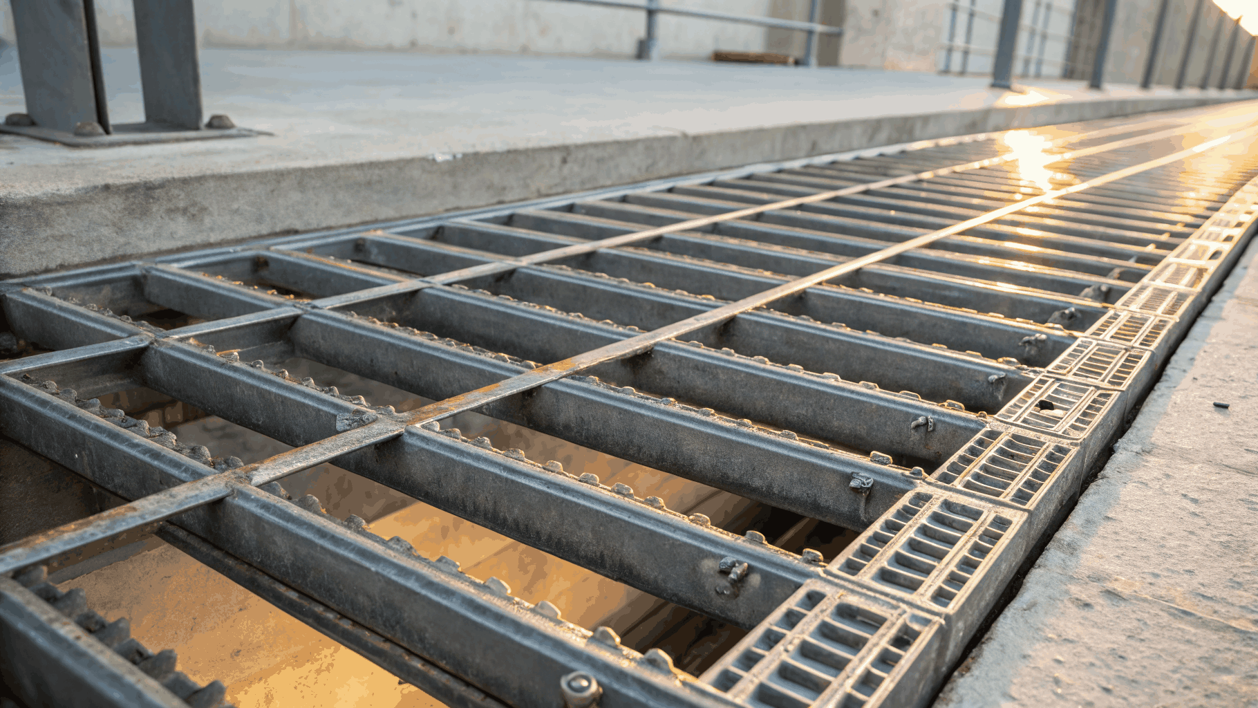
Precision tolerance ±5 µm for fine separation
Standard profiles: 12S, 18S, 22S, 28S, 34S
Duplex 2205 & Hastelloy C-276 upon request
Out-to-in or in-to-out continuous slot flow
Specify wedge wire screens with precision.
Include these verified mechanical tolerances, profile codes, and alloy standards on your purchase orders to ensure exact fabrication and smooth qualification.
Critical Purchase Order Checklist
Mandatory parameters required for error-free quotation and automated production tooling.
| Parameter | Available Industry Range | Manufacturing Tolerance | PO Engineering Clause |
|---|---|---|---|
Slot Opening (Aperture) | 20 µm to 6.0 mm (0.0008 in to 0.236 in) | ±10% for <100 µm, ±0.05 mm for ≥0.50 mm | Specify nominal micron/mm and maximum allowable variation across screen face |
Surface Profile Wire | V-wire profiles (e.g., 12S, 18S, 22S, 28S, 34S, 42S, 60S) | Wire width: ±0.03 mm, Relief angle: 10° to 35° | State wire profile code, surface width, and relief angle for anti-clogging |
Support Rod Pitch & Profile | Round bars (Q25/Q35), teardrop rods, or flat bars at 10 mm to 50 mm pitch | Pitch spacing: ±1.0 mm, Rod angle: 90° ± 0.5° | State internal collapse pressure, differential load, and center-to-center pitch |
Material Alloy & Heat Treatment | AISI 304, 316L, 904L, 2205 Duplex, Hastelloy C-276, Titanium | ASTM A276 / ASTM A580 chemical & mechanical bounds | Require Mill Test Certificate (EN 10204 3.1) and PMI test report |
Dimensional & Flatness Tolerances | Panels, cylinders, sieve bends, or conical baskets | Length/Width: ±1.0 mm, Diagonal squareness: < 1.5 mm, Flatness: < 2 mm/m | Define overall length, outer diameter (OD/ID), ovality, and edge margin |
Edge Treatment & End Fittings | Raw sheared edge, solid framing flats, welded flanges, NPT/BSP threads | Weld seam thickness: ±0.5 mm, Flange hole PCD: ±0.2 mm | Provide dimensional drawing with flange bolt patterns and end weld finishing |
Specify whether continuous slots run along the axis (for axial dewatering) or around the circumference (for rotary drums).
Request Positive Material Identification (PMI) testing on weld zones and support ribs for high-chloride applications.
State required collapse and burst pressure ratings to allow our engineering team to calculate optimum wire-to-rod ratios.
Ready-to-Use Purchase Order Spec Template
PO SPECIFICATION BLOCK: WEDGE WIRE SCREEN
------------------------------------------------------------
Item Description       : Custom Welded Cylindrical Wedge Wire Filter Element
Flow Direction         : Flow-Out-To-In (FOTI) / Surface Wire Outside
Nominal Slot Opening   : 100 Microns (0.100 mm) ± 0.015 mm
Surface Wire Profile   : Profile 18S (Width: 1.5 mm, Height: 2.5 mm, 12° Relief Angle)
Support Rod Profile    : Q25 (Width: 2.0 mm, Height: 3.5 mm) @ 20 mm Pitch
Alloy Grade            : 316L Stainless Steel (UNS S31603) per ASTM A580
Dimensions             : OD 152.4 mm (6.00") x Length 914.4 mm (36.00")
End Fittings           : Top ANSI Class 150 Flange (316L), Bottom Blind Cap Welded
Surface Finish         : Full Acid Pickling & Passivation per ASTM A380
Quality Documentation  : EN 10204 3.1 MTR, Optical Slot Measurement Protocol, PMI Report
------------------------------------------------------------
Paste this block directly into your ERP or purchase order document and update the variables for your specific filter vessel.
Need engineering validation before order release?
Our application engineers review your CAD models, operating temperatures, differential pressures, and slurry abrasive contents to confirm wire cross-sections before manufacturing.
- CAD drawing verification (.DXF / .STEP format)
- Open area (%) vs. hydraulic flow velocity calculations
- Custom flange, collar, and reinforcement ring design
Related Technical Documents & Datasheets
Download verified engineering specifications, tolerance charts, and wire profile catalogs.